This is done to help Indiana High School, my brother and his friends. IASD has served me very well and I think this is a good way to give back a little. IHS lacks a thorough electrical, micro architectural classes; the closest they have is Computer Science, which is good, but not entirely great for building circuitries required for this EV. Thank you Mrs. Baker for your hard work.
Lets get to the topic. This is the package sent to Wasil on Wednesday, March 14th, 2009.
The box contains a complete vehicle, but disassembled. The vehicle body was made with parts around the house including aluminum holiday container (previously contained assorted nuts), and couple smaller aluminum boxes that contained a wallet, and a B.U.M. watch i got back in 1997 (or so). The vehicle was heavy, about 3 lbs, but functional nevertheless.
The reason I did a prototype was 1) I needed to know what kind of logic is the most effective and 2) Something for the team to have as a backup plan (risk mitigation). The reason for 1) is that even though on paper and in pictures the car works perfectly, it doesn't mean that it will when it comes to realization.

For example, I planned to use 2xC batteries for the motor and the other 2xAA batteries for the Arduino microcontroller. It turns out that the H-bridge that I was using takes in 3V but outputs less than desired voltage to the motor (1.9V under load). The H-bridge spec calls for 4.5V minimum motor supply input for a good output. I guess the H-bridge logic for the motors has several resistances that lowers the overall output. So to fix this I had to use 3xAA (4.5V) for the motor and 1xAA for the microcontroller. I couldn't use the C batteries because I only have a battery case for 2xC, and 3xCs would be heavier than I would have liked. I also had to jerry-rigged the battery holders to fit 3xAAs together (picture below).
Be careful with the batteries. One wrong side, or connection, can be detrimental. So look twice before plugging things in, and if you're not sure look at these pictures. I also incorporated a switch to turn on, and off the batteries (picture below).
Note: For the microcontroller battery (1xAA), if you're not running the vehicle on the track, please take out the battery. Since it has a built in 5V regulator, it will drain the battery regardless of usage (picture below). This battery also is modded to only take ONE battery at one side. Failure to do so will burn your fingers off (true story!).
For testing on the computer, the USB cable provides sufficient power to the microcontroller. To test out the motor with USB, you will still need the motor supply (3xAA).
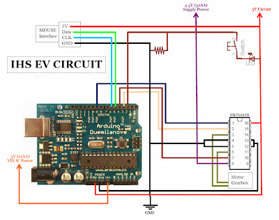
Power connections:
5V IN IC (Red wire from 1xAA battery) connects to the 'Vin' port on the microcontroller (picture below).
4.5V Supply (Red wire from 3xAA batteries) connects to the #8 leg VCC2 of the
SN754110 IC on the breadboard. It does NOT go anywhere else (pictures below). Spec sheet
here (pdf).
Ground (Black wire from the switch) connects to the grounding strip on either side of the bread board where most black wires are hooked up (picture highlight below).
This concludes the introduction to the EV, and how to connect them. Make sure the switch is OFF before connecting/disconnecting any wires! Stay tune for an update on the software side of things. In the meanwhile, check out the video below.


